The welding of Stainless Steel Clad Plate—a composite material combining a carbon/low-alloy steel base layer (e.g., Q345R, SA516Gr70) with a stainless steel cladding layer (e.g., 304L, 316L)—presents a unique metallurgical challenge: welding dissimilar metals.
The primary objective is to achieve a sound structural joint while maintaining the corrosion resistance of the stainless steel cladding layer. This requires meticulous control over welding procedure, particularly regarding dilution (the mixing of base and weld metals), which can severely compromise the stainless steel’s performance.
The guide below outlines the best practices for achieving high-quality welds in stainless steel clad plate applications.
What is Stainless Steel Clad Plate?
The stainless steel clad plate is a bimetallic material made by bonding a high-quality carbon steel or alloy steel base layer with a stainless steel surface layer through methods such as explosive bonding, hot rolling bonding, or detonation + rolling.
It combines:
The corrosion resistance of stainless steel
The high strength and low cost of carbon steel
Higher cost-effectiveness and lighter weight
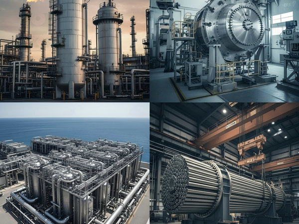
Widely used in industries such as chemical, petroleum, shipbuilding, seawater desalination, pressure vessels, and energy equipment.
Want to purchase stainless steel clad plates or inquire about pricing? Contact Huaxiao Metal for a quote and technical support.
Main Welding & Bonding Methods for Clad Plates
1. Conventional Welding Methods
Traditional welding methods are used in fabrication and joining stages.
Common Types:
- TIG (Tungsten Inert Gas)
- MIG (Metal Inert Gas)
- SAW (Submerged Arc Welding)
Advantages:
- Flexible and widely used
- Suitable for on-site fabrication
Limitations:
- Cannot create full metallurgical bonding
- Risk of weak interface if not controlled
2. Vacuum Electron Beam Welding (EBW)
Vacuum Electron Beam Welding is an advanced technology used in high-end clad plate production.
Working Principle:
- High-energy electron beam melts interface
- Welding occurs in a vacuum environment
- Produces deep and narrow weld zones
Advantages:
- Extremely strong bonding
- Minimal contamination
- High precision
Limitations:
- High equipment cost
- Limited to specialized facilities
👉 Suitable for:
- Nuclear industry
- Aerospace
- High-end pressure vessels
3. Explosive Bonding (Explosion Cladding)
Explosive bonding uses controlled detonation to join two metal layers.
Process:
- Explosive force drives plates together
- High-speed impact creates metallurgical bonding
Advantages:
- Very high bonding strength
- Suitable for large plates
- No melting required
Limitations:
- Surface irregularities
- Post-processing required
👉 Widely used in:
- Heavy industry
- Chemical equipment
4. Hot Rolling Bonding (Most Common Method)
Hot rolling is the most widely used method for manufacturing Stainless Steel Clad Plate.
Process Steps:
- Surface cleaning
- Assembly of layers
- Heating to rolling temperature
- High-pressure rolling
- Metallurgical bonding
Advantages:
- High efficiency
- Good bonding quality
- Suitable for mass production
Key Challenges:
- Rolling force control
- Temperature uniformity
- Defect prevention
Comparison of Clad Plate Manufacturing Methods
| Method | Bond Strength | Cost | Production Scale | Typical Applications |
|---|---|---|---|---|
| EBW | Very High | High | Low | Aerospace, Nuclear |
| Hot Rolling | High | Medium | High | Industrial, Pressure Vessels |
| Explosive Bonding | Very High | Medium | Medium | Chemical, Offshore |
| Conventional Welding | Medium | Low | Flexible | Fabrication |
👉 Hot rolling + advanced bonding is the best balance for most industrial applications.
Principle of Stainless Steel Clad Plate Welding
The fundamental principle governing clad plate welding is sequential, layered, and material-specific welding, strictly separating the fusion of the base metal (high strength) and the cladding metal (corrosion resistance).
Key Welding Tenets:
Layer Separation: The carbon steel side (Base Layer) and the stainless steel side (Cladding Layer) must be welded in sequence, with a highly alloyed Transition Layer acting as a buffer.
Preventing Carbon Migration: High heat input can cause carbon from the base steel to migrate into the stainless steel cladding, leading to Chromium Carbide Precipitation (sensitization) and a loss of corrosion resistance in the cladding layer’s heat-affected zone (HAZ).
Crack Prevention: Special care is required to prevent hydrogen-induced cold cracking in the base steel and hot cracking in the transition and cladding layers.
Main Challenges in Welding Stainless Steel Composite Plates
Successfully welding stainless steel clad plate hinges on overcoming specific difficulties inherent in joining two vastly different metal chemistries. Failure to address these challenges results in compromised structural integrity and corrosion resistance.
Challenge 1: Dilution and Compromised Corrosion Resistance
The Issue: During the fusion welding of the stainless steel cladding, iron (Fe) and carbon (C) from the underlying carbon steel base metal (the less-noble metal) inevitably mix with the stainless steel weld pool. This is known as dilution.
The Consequence: Dilution significantly lowers the Chromium (Cr) and Nickel (Ni) content in the stainless steel weld deposit. This reduction in key alloying elements makes the weld metal less corrosion-resistant than the original cladding and can also lead to the formation of brittle, crack-prone Martensite (especially if high carbon is present).
Challenge 2: Carbide Precipitation and Sensitization
The Issue: Exposure of the stainless steel cladding layer and its Heat-Affected Zone (HAZ) to temperatures between approximately 450℃ and 850℃ (the sensitization range) during welding or Post-Weld Heat Treatment (PWHT).
The Consequence: Carbon within the stainless steel reacts with Chromium, precipitating out Chromium Carbides at the grain boundaries. This depletes the adjacent areas of Chromium, creating Chromium-depleted zones which are highly susceptible to Intergranular Corrosion (IGC).
Challenge 3: Hydrogen-Induced Cold Cracking (HICC)
The Issue: Hydrogen atoms from moisture (in the air, flux, or on the material surface) dissolve into the molten pool. As the base metal (carbon steel or low-alloy steel) cools, the hydrogen atoms diffuse to points of high stress (such as the HAZ) and microstructural defects.
The Consequence: HICC is a structural risk, often occurring hours or days after welding. The trapped hydrogen, combined with the high restraint and hard microstructures (Martensite) common in the base steel HAZ, causes catastrophic, delayed fracture.
Challenge 4: Thermal Stress and Distortion Control
The Issue: Stainless steel (cladding) has a significantly higher Coefficient of Thermal Expansion and lower Thermal Conductivity than carbon steel (base metal).
The Consequence: The differential expansion and contraction during the heating and cooling cycles of welding create immense, uneven residual stresses across the joint interface. This often leads to severe angular distortion (warping) and can compromise the mechanical integrity of the composite bond.
Challenge 5: Hot Cracking Risk in the Transition Zone
The Issue: The transition and cladding layers are susceptible to hot cracking if the weld metal contains high levels of impurities (S, P) or if the solidification path is unfavorable.
The Consequence: Cracks occur while the weld metal is still partially liquid (at high temperatures, near the solidification point). This is mitigated by ensuring the weld metal solidifies into a controlled, dual-phase (austenite + delta ferrite) structure, as excessive fully austenitic structures are less tolerant of impurities and residual stresses.
Joint Design and Groove Preparation of Stainless Steel Clad Plate
Proper joint geometry is the prerequisite for successful clad plate welding.
Groove Types and Design
| Design Parameter | Best Practice Recommendation | Rationale |
| General Geometry | Use Single-V, Single-U, or Double-X grooves. Double-X is preferred for thick sections (> 25mm) to minimize weld volume and reduce angular distortion. | Allows for complete joint penetration and enables welding from both sides. |
| Root Face (Blunt Edge) | A root face of 1 to 2 mm should be maintained, and it must be positioned entirely within the base (carbon steel) layer. | Prevents the root pass from immediately fusing and diluting the stainless steel cladding interface. |
| Root Opening | Typically 2 to 3 mm, depending on the welding process (e.g., SMAW, GTAW) and plate thickness. | Ensures proper penetration and prevents excessive heat buildup. |
Critical Step: Back Gouging
After the base layer welding is complete, the weld root on the cladding side must be mechanically removed via back gouging (e.g., grinding or arc-air gouging).
Gouging Depth: The depth must be sufficient to completely remove the base metal root pass, penetrating approximately 1-2 mm into the original carbon steel-stainless steel interface. This removes slag and any carbon-rich fusion zone formed during the base layer welding.
Surface Cleaning: The gouged surface must be meticulously cleaned (grinding/wire brushing) to remove all slag, carbon residue, and contaminants before the transition layer is deposited.
The Three-Phase Welding Sequence (The Metallurgical Approach)
Welding is executed in three distinct phases, each requiring specific materials and procedure control.
Phase I: Base Layer Welding (Carbon Steel Side)
| Procedure Variable | Specification | Metallurgical Goal |
| Welding Process | SMAW (Shielded Metal Arc Welding), SAW (Submerged Arc Welding) | Provides necessary strength and productivity. |
| Filler Metal | Matched to the base material (e.g., E7018, ER70S-6 for Q345R/SA516Gr70). | Achieve the required structural strength and toughness of the base plate. |
| Preheating | Mandatory for thick or low-alloy base metals (e.g., 100℃ to 200℃ minimum). | Reduces cooling rate to prevent Hydrogen-Induced Cold Cracking (HICC). |
| Interpass Temp | Strictly controlled, often max 200℃ to 250℃ for the base layer. | Prevents excessive carbon diffusion towards the stainless steel interface. |
Phase II: Transition Layer Welding (The Dilution Buffer)
This is the most critical stage, where a high-nickel (Ni) buffer layer isolates the carbon steel from the stainless steel.
| Procedure Variable | Specification | Metallurgical Goal |
| Welding Process | GTAW (Gas Tungsten Arc Welding) or SMAW are often used for precision. | Provides controlled heat input and precise bead placement. |
| Filler Metal (Crucial) | High-Nickel Alloys or High-Chromium/Nickel Alloys, typically E309L or E309LMo series. | The high Ni content in 309L (approx. 12-15%) effectively dilutes the Fe and C from the base metal, ensuring the weld deposit remains austenitic-ferritic and free of brittle martensite. |
| Layer Quantity | At least 1 to 2 layers are required. | Ensures the transition layer’s composition is stable and robust enough to prevent carbon migration into the final cladding pass. |
| Dilution Control | Minimum heat input, fast travel speed. | Minimizes the mixing of the carbon steel and the filler metal, reducing the risk of a brittle or corrosion-prone transition zone. |
Phase III: Cladding Layer Welding (The Corrosion Barrier)
The final layer restores the full corrosion resistance of the stainless steel.
| Procedure Variable | Specification | Metallurgical Goal |
| Welding Process | GTAW (TIG) or SMAW are common. | GTAW is often preferred for the surface pass for better aesthetics and defect control. |
| Filler Metal | Matched to the cladding alloy (e.g., E316L for 316L cladding; E308L for 304L cladding). | Guarantees the surface weld metal has the same corrosion resistance as the cladding plate. |
| Interpass Temp | Strictly controlled, often max 150 ℃ to 200 ℃. | Low interpass temperature is critical to prevent sensitization (chromium carbide precipitation) in the stainless steel HAZ. |
| Technique | Stringer beads, minimal weaving. | Ensures low heat input to preserve corrosion resistance. |
Post-Weld Heat Treatment (PWHT) and Quality Assurance
Post-Weld Heat Treatment (PWHT)
PWHT is typically required by code (e.g., ASME, NB/T 47002) to relieve residual stresses in the base metal, especially for pressure vessel applications.
Temperature Range: Generally between 580℃ and 650℃.
Metallurgical Impact: PWHT can potentially cause sensitization in the stainless steel layer (carbide precipitation). Using low-carbon grades (L-grades like 304L/316L) is essential to mitigate this risk.
Procedure: Heating and cooling rates must be slow and controlled to prevent distortion and microstructural damage.
Non-Destructive Examination (NDE)
All clad plate welds must undergo rigorous NDE to verify integrity:
Base Layer: Ultrasonic Testing (UT) and/or Radiographic Testing (RT) to ensure structural soundness and complete fusion.
Cladding Layer (Surface): Liquid Penetrant Testing (PT) to detect surface cracks and porosity, ensuring the corrosion barrier is intact.
Interface Integrity: UT may be used to verify the integrity of the bonding interface in the vicinity of the weld.
Defect Prevention and Control of Welding Stainless Steel Clad Plate
Hot Cracking in Cladding/Transition Layers
Cause: The formation of low-melting-point eutectics (often related to sulfur or phosphorus) at grain boundaries during solidification. High dilution with carbon steel can also make the structure prone to cracking.
Prevention: Use high-purity filler metals (low S/P content) and high-nickel transition filler metals (309LMo), and strictly control the heat input. Ensure the weld metal contains a small, controlled amount of Delta Ferrite (3%–10%), which acts to absorb impurities and prevent crack propagation.
Cold Cracking (Hydrogen Embrittlement)
Cause: Hydrogen trapped in the base metal during welding, high restraint, and brittle microstructures (martensite).
Prevention: Mandatory preheating (Phase I), use of low-hydrogen filler metals (e.g., E7018), and controlled cooling rates. Ensure the welding environment is free of moisture.
Intergranular Corrosion (Sensitization)
Cause: Heating the stainless steel above 450℃ to 850℃ (e.g., during multi-pass welding or improper PWHT) causes chromium and carbon to combine, depleting chromium near the grain boundaries.
Prevention: Use L-grade (Low Carbon) stainless steel (304L/316L) as cladding and filler metal, strictly control the interpass temperature (Phase III), and ensure the PWHT procedure is optimized.
Typical Application Fields
The increasing stringency of environmental regulations worldwide has made Stainless Steel Clad Plate an indispensable material in pollution control equipment, particularly in Flue Gas Desulfurization (FGD) systems within the power generation sector.
| Application Sector | Typical Equipment | Core Requirement & Clad Solution |
| Flue Gas Desulfurization (FGD) Systems | Absorber towers, chimney linings, ductwork, and slurry tanks. | Requirement: Extremely high resistance to acid corrosion(Sulfuric Acid H2SO4) and erosion from slurry. Solution: Cladplates utilizing high-performance stainless steel or Duplex/Super Duplex alloys (e.g., 2205 or 2507) as the cladding layer, bonded to a structural base like Q345R. This provides the necessary chemical resistance without the prohibitively high cost of solid Duplex steel. |
| Water Treatment Facilities | Industrial wastewater tanks, clarifiers, and piping sections. | Requirement: Durable resistance to various chemical dosing agents and continuous exposure to moisture. Solution: Standard 304L or 316L clad plates offer an excellent combination of corrosion resistance and fabrication ease for large-volume structures. |
This addition significantly enhances the content’s relevance to the Power Generation and Environmental sectors, which are major consumers of clad plates.
FAQ about Stainless Steel Clad Plate Welding & Manufacturing Guide
What is the best method for clad plate manufacturing?
Hot rolling is the most commonly used method due to its balance of cost, efficiency, and bonding quality.
What is electron beam welding in clad plates?
It is a high-precision welding method that uses an electron beam in a vacuum to create strong metallurgical bonding.
What causes delamination in clad plates?
Delamination is caused by poor bonding conditions, insufficient pressure, or surface contamination.
Which industries use clad plates?
Clad plates are widely used in oil & gas, chemical, marine, and power industries.